APSX-NANO CNC Software Overview
 |
| -Click to Go Back |
APSX-NANO CNC Swiss Lathe comes with the APSX CNC software. Import your design file using a USB memory stick, choose your file from the File tab, and load it to the machine. You will see the part design in the perspective view.
There is NO subscription fee for the software. Do not worry about the system requirements because the software is already installed on the PC that comes with the APSX-NANO. Finally, the APSX CNC software does not require an internet connection to operate. It runs with G-code (.gcode) files.
User Interface
The software has a layout structure that makes CNC Swiss Lathe operation much easier.
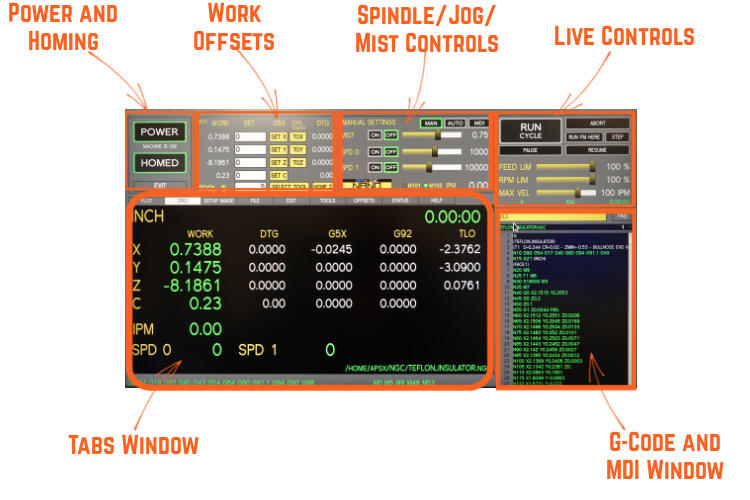
Power and Homing Window
The APSX NANO is designed to be conveniently powered through a standard 120V wall outlet. However, to ensure uninterrupted operation, it is highly recommended that the machine be connected to its own dedicated circuit on the circuit breaker panel, with no other appliances drawing power from that particular circuit.
For customers located outside of the United States, where the power supply may be 220V, a step-down power converter rated at 220V to 120V is required for operation in regions such as Europe or other similar places. We advise the use of a 3000W converter, with various options available on the market, including the Rockstone Power RSP-3000.
To initiate the startup process, please follow these steps:
- Begin by plugging the power cord of the APSX NANO into the designated wall outlet.
- Subsequently, connect the power cord of the monitor to its respective power source.
- Turn on the cordless keyboard by removing the plastic battery strip and flipping the switch located on the right side of the keyboard.
- Connect the keyboard's USB interface to the control panel's USB port. The Keyboard touchpad serves as a functional replacement for a standard PC mouse, enabling seamless control of the mouse arrow.
- Locate and press the "PC Power" button positioned at the bottom right corner of the control panel once.
- The machine will now initiate the booting process and automatically launch the APSX software.
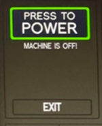
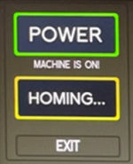
Homing
Click on the blinking Press To POWER and then click on the blinking Home All buttons
| - |  | - | 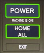 | - |
It will be blinking in Yellow during the homing. In the end, it will show as Homed. You can click on HOMED button whenever you need homing.
| - |  | - | 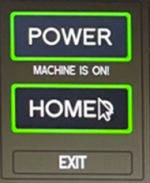 | - |
When using the EXIT button, the machine will save the G54 coordinates homing positions based on your workpiece.
When you are done using the machine, you can unplug the power cord from the wall outlet if you do not need to keep the homing coordinates.
Work Offsets Window
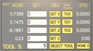
They are also called G54 work offsets. That defines the work coordinates for the g-codes. You can either type these desired coordinates and hit enter or click on the SET buttons for each axis. Default settings are always zero.
Manual Controls
Mist Control
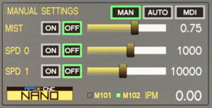
Click the MIST ON (M7) button to turn on air and mist (air and mist are now active). Control the mist amount by clicking/dragging the Mist Amount tab. To run the air without mist, click the MIST ON button and drag the Mist Amount tab to the left below 0.45. Any value above 0.45 will activate and increase the mist amount. M9 turns it off.
Spindle Control
Spindle 0 is the main spindle on the z-axis. Spindle 1 is the live tool on the x-axis and it is only clockwise (CW). Click the SPINDLE ON button to turn on the spindle in manual control. It is a similar move as to M03, M04 and M05. Next, control the RPM by clicking/ dragging the Spindle RPM tab.
To set the speed of the spindle 0 to 1000 RPM, use M3 S1000 $0 (CW 1000RPM for the main spindle) and to turn it off use M5 $0. To set the speed of the spindle 1 to 10000 RPM, use M3 S10000 $1 (CW only) and to turn it off use M5 $1.
M101 and M102
There are two modes of operation: Angle Mode (M101) and Spindle Mode (M102)
Angle Mode (M101): G0 C180 for precision rotating the workpiece. It is generally used with spindle 1 live tooling.
Spindle Mode (M102): It is for normal lathe operations for continuous rotation. The default mode is Spindle Mode (M102) when the machine starts. Before switching from Angle Mode to Spindle Mode, make sure that C position is set to zero. The C position information is lost when switching to Angle Mode.
Jogging Control
Pendant - Jogging
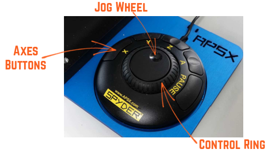
The pendant allows precise control of the machine's travel speed. For example, manually touching off the end mill to your workpiece and zeroing the X, Y and Z-axis requires small adjustments at low speed. It increases efficiency on the jobs that require a difficult setting of the workpiece and the tool.
PRESS AND HOLD X, Y, or Z buttons and rotate the Controller Ring clockwise for positive continuous travel, rotate counterclockwise for negative travel.
Step jogging is done with the Jog Wheel for jogging in very small increments by pressing and holding the X, Y, or Z buttons.
Cycle Control Window
These controls are available to use while running a g-code program.
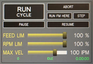
Run Cycle
It starts the program. While it is ON, the green light around the button illuminates.
Abort
It exits the program and stops all motion including the spindle.
Run From Here
Click on the FIND button to open the dialog box. Type the keyword that you want to find in the g-code. It will highlight the keyword(s) in the g-code for you. When you click on it, you can use the Run From Here button to run the program starting from that line.
Step
It executes the g-code one line at a time. You need to click on PAUSE button first then click on STEP button each time. Go cancel this mode, click on RESUME button.
Pause
It pauses the g-code. If you click on the RESUME button, it will continue.
Feed Override Limit
Changes the IPM (inches per minute) defined in the G-Code by the percentage selected on the slider. This will affect G01 (feed) codes not on G00 rapid moves.
Spindle RPM Override Limit
Changes the spindle RPM defined in the G-Code by the percentage selected on the slider. This will affect G01 (feed) codes not on G00 rapid moves. The spindle must be running for these controls to have a noticeable effect. The override doesn’t drive the spindle past its maximum speed.
Max Velocity
Adjustable maximum speed for any move (G01 and G00). The slider can be very useful when running a G-code program for the first time. You can use it to stop the mill by sliding it down to 0 and verifying the Distance to Go and X/Y/Z/A DROs look appropriate before continuing.
The Last Row Number Stopped, Status and the Cycle Time
The last row number stopped shows the number when the program is aborted or paused. The status shows the current status of the machine such as idle or running. The last number on the right corner show the cycle time.
G-Code and MDI Window
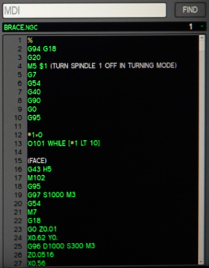
Recent Files Drop-Down Menu
It displays the currently loaded g-code file. When you click on it, you can see the last files that have been loaded.
MDI Line
You can send commands to the machine directly by typing a command into this Manual Data Input line (MDI) window. Then you need to press ENTER to execute. You can press the ESC to abandon it. Recent commands are stored for reuse.
Find
You can search text in the g-code file for numbers, codes, or speeds etc. Click on the FIND button to open the popup window. Type the keyword to search and click on the find button there. If you select the check box, the findings will be highlighted.
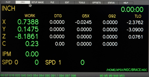
Tabs
The user interface has a TABS set that includes tables, buttons, and digital readouts (DROs) for specific purposes. These tabs are PLOT, DRO, SETUP IMAGE, FILE, EDIT, TOOL, OFFSETS, STATUS, and HELP.
PLOT tab
The PLOT tab displays a graphic representation of the work coordinates and the toolpath in the g-code loaded. The preview lines are in white, and the toolpath as it is milled is red in color. There are preview buttons on the side: ZOOM, PERSPECTIVE, VIEW X-Y-Z, and CLEAR.
Special comments can be inserted into the G-Code file to control how the preview of AXIS behaves.
- Left mouse button to PAN the screen
- Right mouse button to ROTATE
- ZOOM+ and ZOOM- button to zoom in and out
- CLEAR to remove the machining moves
- PERS button to view the perspective view

DRO tab
This tab shows detailed information in a dashboard style. For example, you can see the current unit inch or mm. The work coordinates are in the first column. The active G coordinates are also on this tab. The current IPM and RPM values are on the lower-left corner. The active file location is listed in the lower right corner. Finally, the duration of the g-code is placed in the top right corner.
Special comments can be inserted into the G-Code file to control how the preview of AXIS behaves.
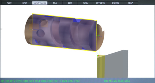
SETUP IMAGE tab
If you create and save a picture with the same file name as the g-code program, it will show it on this tab. The picture file name should have png extension (lower case) at the end. You can show the setup layout and add some critical notes to it. The idea is to make the setup process easier for you by using this cheat sheet.
FILE tab
When you insert the USB memory stick into the control panel, it will show its content on the USB drive window's left side of this tab.
Using the COPY buttons, you can move the files to and from the hard drive window on the right. When the file is on the right side (on the hard drive window), you can double click on it or click on the LOAD G-CODE button to load it. It will show up on the g-code panel on the right side of the screen.
Click the EJECT USB button to disconnect the USB drive from the controller.
NOTE: Ejecting the USB drive helps to avoid corrupting data on the USB drive.
IMPORTANT: For software to accept and read your G-Code file, it must end with extension .ngc (lower case). Please configure your 3D design software to create all G-Code files with this extension.
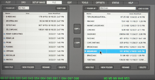
The FOLDER UP buttons on both windows can be used to navigate through the file structure.
You can use the NEW FOLDER, NEW FILE, RENAME and DELETE buttons at the bottom of the window for file management.
EDIT tab
You can edit the loaded g-code file in this tab. Then, when you make a change and save it, the loaded file will also be updated instantly. Use the FIND button to find the specific code you need to change. Then SAVE the file. Or SAVE AS a different file name.
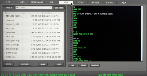
The FOLDER UP button can be used to navigate through the file structure.
You can use the NEW FOLDER, NEW FILE, RENAME and DELETE buttons at the bottom of the window for file management.
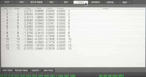
TOOL tab
The Tool tab displays the tool table. Tool offsets allow the operator to use tools of different lengths in different tool locations while still programming with respect to the workpiece. You can switch tools quickly, without the need to set up the mill every time a tool is mounted. The current tool's offset values are in the DRO tab (TLO) for you to see at anytime.
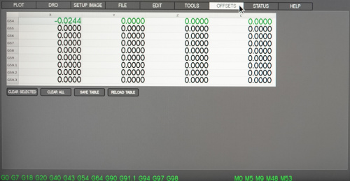
OFFSETS tab
The Offsets Table displays the current offsets for the active work coordinates. If you have different workpieces, you can use the other G5X coordinates available. The current G5X values are in the DRO tab for you to see at anytime. To alter a value in the table, mouse-click twice on the field that you’d like to edit. When you finish entering the desired new value, click Enter key on the keyboard to accept the value.
STATUS tab
The Status tab displays the list of notifications on the right side window. On the left side, there is a list of active g-codes in green color.
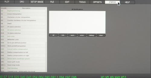
Status values can also be seen on the control panel LED display.
- 000 – OK
- 111 – Spindle overload
- 222 – Stepper motor stall
HELP tab
The Help tab displays the list of frequently used MDI commands, keyboard shortcuts for Cycle Controls and X-Y-Z coordinate layout on the machine.
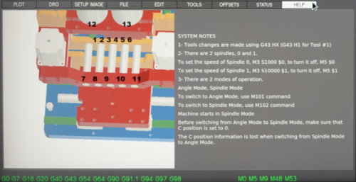
The current G-codes and M-codes are the ones actively being used on the machine.